User Guide
This guide explains how to drive the IoT Emulator from its web interface — first the two modes it offers, then a guided walk-through, a set of task-oriented recipes, and finally a complete reference for every panel and control.
|
New here? Start with Operating Modes to pick the mode that fits your job, run your first simulation with Getting Started, then follow the matching recipe in Common Workflows. The remaining sections are a field-by-field reference for each part of the UI. |
Operating Modes
Opening the emulator at http://localhost:8556 no longer drops you straight into the device table: the root URL serves a landing page where you pick how you want to work.
| Mode | Use it for | URL |
|---|---|---|
Load Test Mode |
Many devices driven together from one shared configuration — group/concurrent/delay settings and a single Initialize tree / Start cycle for all of them. This is the classic emulator screen documented in Load Test Mode — Web Interface Overview. |
|
Single Emulator |
Individual devices, each with its own target server, device tree, protocol and security settings, started and stopped independently. See Single Emulator Mode. |
|
Both modes drive the same emulator instance and the same REST API, so devices created in one mode also show up in the other. The landing-page footer shows the running build (hover it for build time and commit) and links to the Swagger UI.
The pages stay reachable under their file names as well — /index.html (Load Test), /single.html and /landing.html.
|
Getting Started
This walk-through takes you from a freshly started emulator to a running device simulation in Load Test mode. For a single device with its own server and data model, follow Run Individual Devices Side by Side instead.
|
These steps assume the emulator is already running and reachable at |
-
Open the Web UI at
http://localhost:8556and choose Load Test Mode on the landing page (or go straight tohttp://localhost:8556/load). The header shows whether this page can reach the emulator, the running build, and links to the API docs and to this guide; the arrow at its left leads back to the mode selection. -
Pick a protocol in the toolbar (LWM2M, MQTT, CoAP, USP, FSH_HUB or DUSUN). See Supported Protocols for protocol-specific defaults.
-
Set the target server — enter the IP and Port of the server you want to emulate against (ACS, LWM2M server, MQTT broker, …). Leave the client IP as
0.0.0.0unless you need a specific local interface. -
(Optional) Choose a data model — in Device tree (XML), select the
*_resources.xmlthat defines the device parameter tree. The built-in file for the selected protocol is used by default. -
(Optional) Set how many devices — under CPE Amount, set Groups, Concurrent and Delay to simulate more than one device. See Simulate Multiple Devices.
-
Save settings — store the configuration with the Save settings button (most fields also persist automatically on change).
-
Initialize tree — builds the device data model in memory. The status changes to Initialized.
-
Start — the emulator registers the device(s) with the target server and the status becomes Running.
-
Watch the Logs panel — the protocol messages the devices receive (
IN) and send (OUT) stream in real time, with aUIrow for each action you take on the page. Click any row for the full payload. See Logs. -
When finished, click Stop — it disconnects every device of the run and returns the emulator to its initial state.
Common Workflows
Task-oriented recipes for the most frequent jobs. Each one links to the detailed reference further down the page.
Run Individual Devices Side by Side
When each device needs its own target server, data model or credentials, use Single Emulator mode instead of the group settings:
-
Open
http://localhost:8556/single(or pick Single Emulator on the landing page). -
Fill in Client ID / Endpoint, Serial Number and the Server IP / Server Port of that device’s target server; optionally pick a Device tree (XML) and expand Security for PSK or X.509 credentials.
-
Click Start Emulator. The device is created, initialized and started on its own — no global Initialize tree / Start is needed and the devices already running are untouched.
-
Change the fields (at minimum the Client ID) and click Start Emulator again to add the next device.
-
Stop, Start or Delete each device from the Active Emulators list.
Every device created this way is written to configuration/devices.json, appears in the Device library, and is recreated automatically the next time the emulator session is initialized. Full reference: Single Emulator Mode.
Simulate Multiple Devices
Use the CPE Amount controls in the toolbar to scale beyond a single device:
-
Groups — number of device groups to create.
-
Concurrent — how many devices connect at the same time.
-
Delay — seconds to wait between registrations (spreads load on the target server).
Beside the CPE Amount title the page shows the total the two fields make — Groups × Concurrent devices, which is what Initialize tree creates once Save settings has sent the values — and calls it a large run, in the warning colour, above 1000 devices. That threshold is a hint, not a limit.
Set the values, then Initialize tree and Start as usual. Every device appears as a row in Active Devices.
For large counts, raise the JVM heap — see JAVA_OPTS.
|
Replay a Real Device Tree from an ACS Database
Instead of the bundled *_resources.xml, the emulator can pull a parameter tree from an existing device record. Full field reference: Extract CPE from DB.
In the web interface this is the Extract CPE from DB section in the left column. The emulator must reach the database over the network (from its pod, when it runs in Kubernetes). The shipped image carries the MySQL driver only.
Generate Telemetry with Autoupdate
To make a parameter change on its own while the emulator runs (e.g. a fluctuating sensor reading), give it an Autoupdate config: a numeric range with a step and a period, or a pipe-separated Dataset (v1|v2|v3) to cycle through fixed values, optionally applied to every device that owns the same parameter. Detailed fields: Set a Parameter Value.
In the web interface this is the Autoupdate section under Set value; it works for session devices and for devices started from Single mode.
Customize Behaviour with Rules
A rule runs JavaScript on every parameter update of every device, whatever the rendering — the body of onParamUpdated(param, device, ctx), persisted to rules.js. In the web interface it is edited in the Rules dialog (controls bar). See Rules.
Export and Import a Device Set
Capture the current device list and parameter values, then restore them later. The set is kept on the server, in configuration/snapshot.json; nothing is downloaded to the browser.
-
Export device set — writes
configuration/snapshot.json. -
Import device set — restores it (only when the emulator is stopped/reset).
See Active Devices. The same actions are available over REST — see Snapshot endpoints.
Drive the Emulator over REST
Every UI action has a REST equivalent for scripting and CI. The base URL is http://localhost:8556/api and Swagger UI is at http://localhost:8556/swagger-ui.html.
# Initialize and start, then list active devices
curl -X POST http://localhost:8556/api/init
curl -X POST http://localhost:8556/api/start
curl -s     http://localhost:8556/api/devices
Full reference: REST API.
Single Emulator Mode
Single Emulator mode (/single) drives devices one at a time. Each device carries its own target server, device tree, protocol and security settings; it is created, started, stopped and deleted independently of the others; and its configuration is persisted, so the same set of devices comes back after a restart.
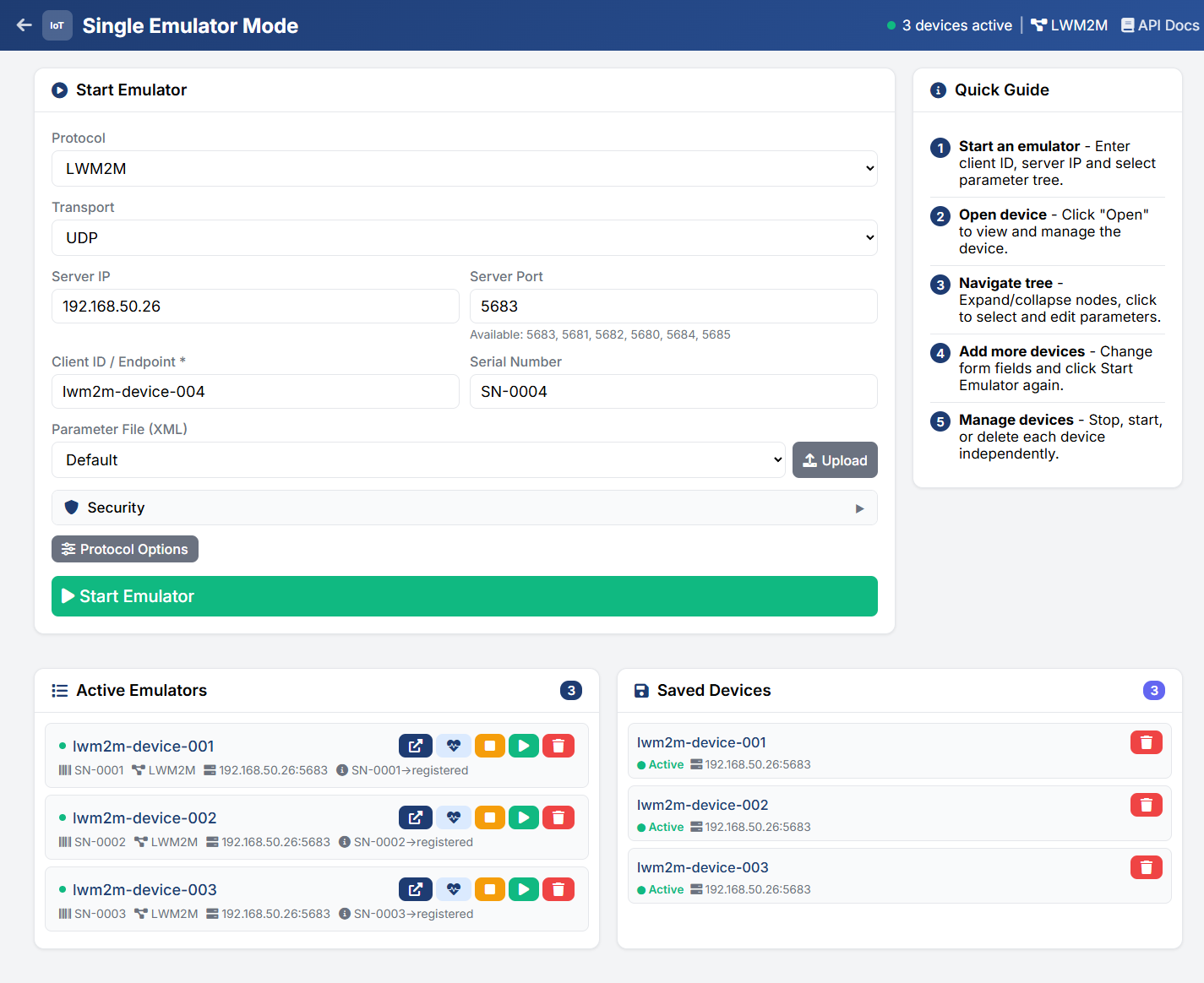
The screen has four areas:
| Area | Description |
|---|---|
Header |
Back arrow to the landing page, the number of devices currently running and how many of them are connected to their servers (for example |
Start Emulator (top left) |
The form that defines and launches one device — see Start Emulator Form |
Quick Guide (top right) |
Five-step reminder of the workflow: start an emulator, open the device, navigate the tree, add more devices, manage them |
Active Emulators (bottom left) |
The devices currently held by the emulator, with per-device actions — see Active Emulators |
Device library (bottom right) |
The device configurations persisted to |
Both lists refresh on their own: active devices every 5 seconds, stored configurations every 15 seconds. The refresh pauses while the browser tab is hidden and catches up as soon as it is shown again.
Start Emulator Form
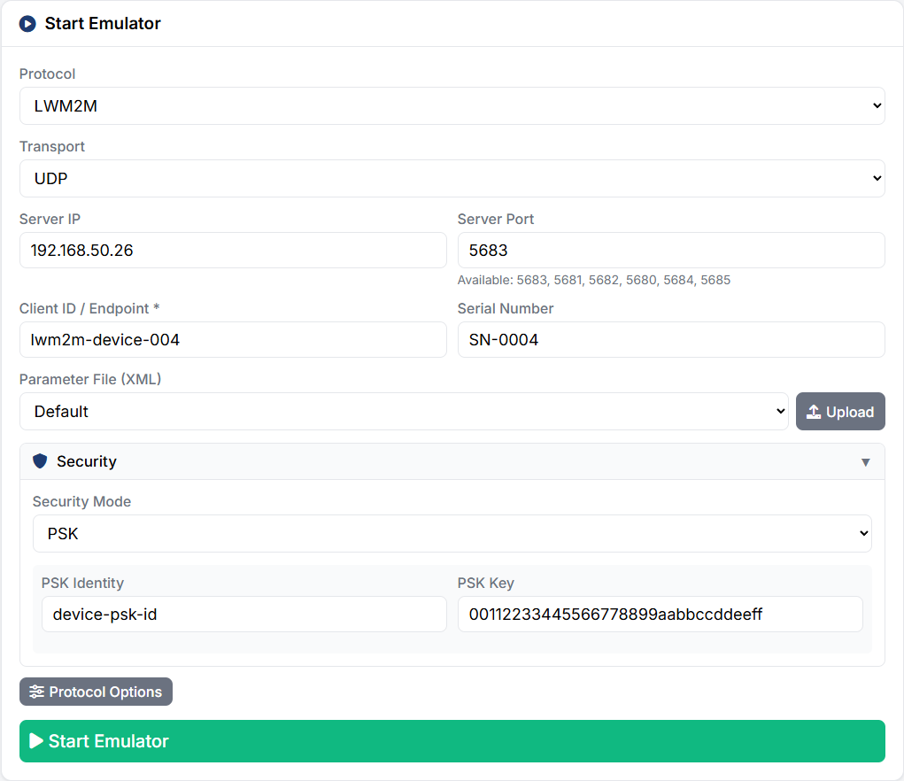
| Field | Description |
|---|---|
Protocol |
Protocol for the device (LWM2M, MQTT, CoAP, USP, FSH_HUB, DUSUN). Changing it switches the emulator’s active protocol and reloads the transport options below. |
Transport / MTP Type |
Only shown for protocols that offer a transport choice — UDP/TCP for LWM2M, STOMP/CoAP/WebSocket/MQTT for USP. The label follows the protocol, and the value is passed to the device as a protocol option. |
Server IP |
Target server for this device. Left empty, the device falls back to the server from the global configuration. |
Server Port |
Port on the target server. The hint under the field lists the ports declared for the selected transport (for example |
Client ID / Endpoint (required) |
Endpoint name of the device. It must be unique — creating a second device with the same ID is rejected. |
Serial Number |
Serial number reported by the device. Defaults to the Client ID when left empty. |
Device tree (XML) |
The |
Security |
Collapsible section with the Security Mode — |
Protocol Options |
Opens the protocol options dialog — see Protocol Options. |
Start Emulator |
Creates the device from the form, initializes and starts it in one step ( |
Protocol Options
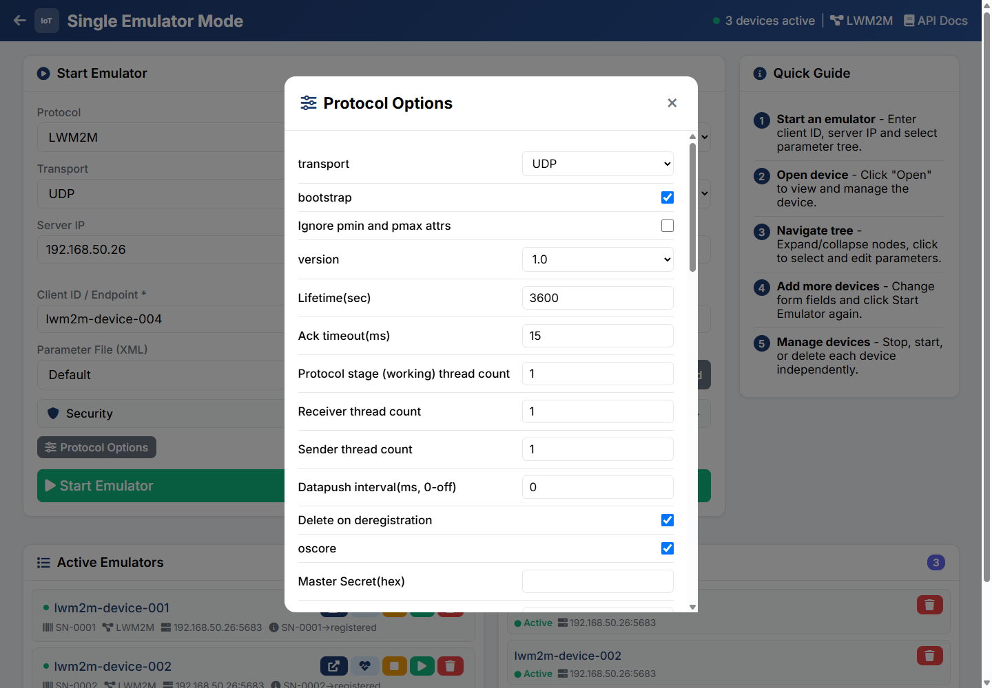
The dialog renders the options declared in <protocol>_gui.properties for the active protocol as checkboxes, dropdowns and text fields — for LWM2M for instance transport, bootstrap, version, Lifetime(sec), the thread counts and the OSCORE keys. Save writes them through POST /api/protocolOptions so they apply to the devices started afterwards; Cancel discards the edits.
Active Emulators
Each device is one card showing its Client ID, serial number, protocol, serverIp:serverPort, a security badge when the mode is not UNSECURE, and the live status reported by the protocol stack (for example SN-0001→registered or SN-0001→no connection).
Each card also carries a connection badge — a coloured dot and a word saying whether the device is connected to its own server, as its protocol reports it. Hover the badge for the same explanation.
-
Connected (green) — the device’s server accepted it: for LWM2M the server accepted its Register or an update, for USP the controller answered its OnBoardRequest, sent its Get of
Device.with late registration, or sent it any other request, for MQTT, FSH_HUB and DUSUN the broker accepted the connection. -
Not connected (red) — the device is not connected to its server now: stopped, not registered yet, a registration or an update that failed or timed out, deregistered, or a lost MQTT session. A USP device with onboarding or late registration on is Not connected whenever its controller has not confirmed it: before the first confirmation, and after a registration or MTP send error, stop, restart, reboot or factory reset, until the controller confirms it again.
-
Unknown (grey) — the device’s protocol does not report it. CoAP devices always show Unknown: they have no handshake with their server. A USP device with both onboarding and late registration off is Unknown whenever its controller has not confirmed it: before the controller’s first request, and again after every registration or MTP send error, stop, restart, reboot or factory reset, until the controller’s next request.
A USP device keeps Connected when its MTP connection drops and no further traffic arrives: the emulator does not detect that.
The status line and the badge can disagree — an MQTT device’s status keeps reading connected after the broker drops it — and the badge is the one to go by. The header’s count of connected devices counts the cards that read Connected.
| Action | Description |
|---|---|
Open |
Opens the device detail dialog with its parameter tree — see Device Detail and Parameter Tree |
Heartbeat |
Sends a registration update for this device only |
Stop |
Stops this device; the others keep running and its entry in the device library is kept |
Start |
Starts a device that was stopped |
Delete |
Stops the device and removes it from both the active list and the device library |
Device Library
Every device created in this mode is written to configuration/devices.json. The Device library panel lists those stored configurations with their state (Active when the device is currently held by the emulator, Offline otherwise), protocol, target server and security mode.
-
Start — shown for offline entries only: recreates the device from its stored template and starts it.
-
Remove — removes the configuration from the library; a running device with the same ID is left alone.
Devices in the library are recreated automatically when the emulator session is initialized, so restarting the container brings the same devices back.
Device Detail and Parameter Tree
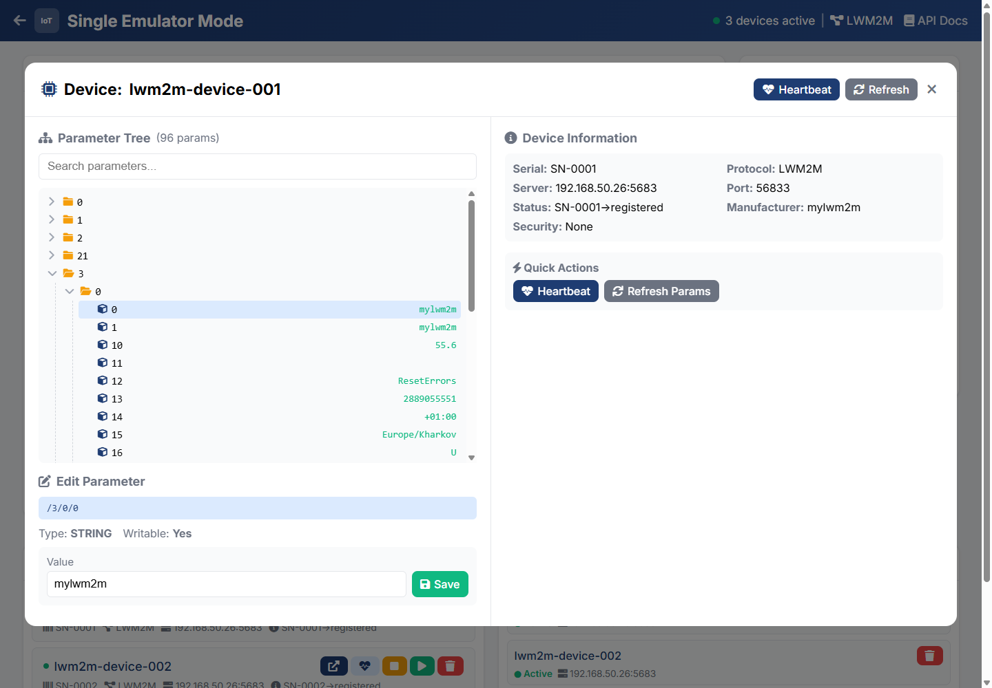
Open on a device card opens a dialog built from four blocks:
-
Parameter Tree — the device’s parameters as a collapsible tree (
/3/0/0-style paths for LWM2M, dotted paths for USP/TR-181), with the parameter count in the header, a Search parameters… filter and the current value next to each leaf. -
Set value — appears once a leaf is selected: the parameter path, its type and writability, the Value field, and Set value, which pushes the new value into the running device (
PUT /api/devices/{clientId}/parameters/{paramName}). A parameter a rule has frozen shows Writable: No, and Set value is disabled for it: the emulator does not accept a new value. -
Device Information — serial number, target server, live status, security mode, protocol, local client port and manufacturer.
-
Quick Actions — Heartbeat (registration update for this device) and Refresh Params (re-read the tree from the device).
Close the dialog with the X in the header or by clicking the dimmed backdrop.
Load Test Mode — Web Interface Overview
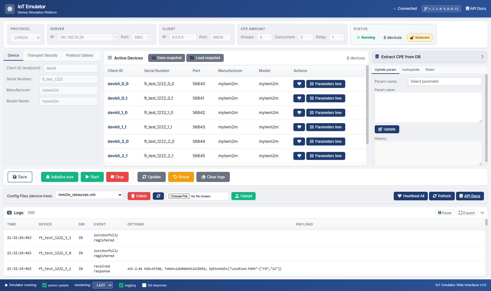
Load Test mode is the classic emulator screen: one shared configuration applied to every simulated device, with Groups / Concurrent / Delay for scaling up and a single Initialize tree / Start cycle for all of them. Open it from the landing page or directly at http://localhost:8556/load.
| This section and every section below it describe Load Test mode. The per-device screen is documented in Single Emulator Mode. |
The interface is divided into several functional areas:
| Area | Description |
|---|---|
Header |
Back arrow to the landing page, application title, whether this page can reach the emulator, running build, and links to the API docs and to this guide |
Toolbar |
Protocol selection, server/client configuration, CPE amount, and status |
Left Panel |
Device settings, transport security and protocol options |
Center Panel |
Active devices list with actions |
Right Panel |
Set value — push a new value into the selected parameter; Autoupdate and History for the same parameter below it |
Control Bar |
Main action buttons (Save settings, Initialize tree, Start, Stop, Heartbeat all, Clear logs) |
Device tree bar |
The Device tree (XML) the next Initialize loads, its upload and delete, and Refresh — see Quick Actions |
Logs Panel |
Live stream of raw protocol messages ( |
Footer |
Status indicators and rendering options |
Toolbar
The toolbar at the top provides quick access to essential settings.
Protocol Selection
| Field | Description |
|---|---|
Protocol |
Select the communication protocol: LWM2M, MQTT, CoAP, USP, FSH_HUB, or DUSUN |
Server Configuration
| Field | Description |
|---|---|
IP |
IP address of the target server (e.g., ACS, LWM2M server) |
Port |
Server port number (default varies by protocol) |
Client Configuration
| Field | Description |
|---|---|
IP |
Local IP address for the emulator client (usually 0.0.0.0) |
Port |
Local port for the emulator client |
Device Configuration
The left panel contains tabs for device settings.
Device Tab
| Field | Description |
|---|---|
Client ID (endpoint) |
Unique identifier for the device endpoint |
Serial Number |
Device serial number |
Manufacturer |
Device manufacturer name |
Model Name |
Device model identifier |
Transport Security Tab
Configure security settings for the connection:
-
Unsecured — No encryption
-
PSK — Pre-Shared Key authentication
-
PSK ID — Identity string
-
PSK Key — Hexadecimal key value
-
-
Certificate — X.509 certificate authentication
-
Key Store Path/Password
-
Trust Store Path/Password
-
Certificate Alias/Password
-
Protocol Options Tab
Protocol-specific settings rendered dynamically from {protocol}_gui.properties. Values are persisted to the server-side properties file immediately on change — there is no need to click Save settings afterwards.
Examples per protocol:
-
LWM2M — registration lifetime, binding mode, queue mode, bootstrap settings
-
USP —
mtp(STOMP / CoAP / WebSocket / MQTT) together with a pairedportselector,usp.mtp.mqtt.qos,usp.mtp.ping_interval, content type, WebSocket sub-protocol -
CoAP / MQTT / FSH_HUB / DUSUN — protocol-specific keepalive, QoS, topic patterns and so on
For USP, the MTP selector (STOMP/CoAP/WebSocket/MQTT) lives in this tab — picking an MTP value also enables the matching port dropdown.
|
Quick Actions
The bar under the control buttons holds the device tree picker and Refresh.
| Button | Description |
|---|---|
Refresh |
Refresh the current status and the device list |
Heartbeat all is one of the Control Buttons, and API Docs and User Guide are links in the header.
Active Devices
The center panel displays all active simulated devices in a table:
| Column | Description |
|---|---|
Client ID |
Device endpoint identifier |
Serial Number |
Device serial number |
Port |
Local port used by the device |
Manufacturer |
Device manufacturer |
Model |
Device model name |
Connection |
Whether the device is connected to its own server, as its protocol reports it: Connected, Not connected or Unknown — the same badge, with the same tooltip, as on the Single page’s cards (see Active Emulators). CoAP devices always show Unknown. |
Actions |
Heartbeat (icon) and Parameters tree (icon + label) buttons |
Click Parameters tree on a device row to open a large modal listing every parameter of that device — see Parameters Tree Viewer.
The header above the device table shows how many devices are listed, and also exposes:
-
Export device set — write the current device list and parameter values to
configuration/snapshot.jsonon the server (nothing is downloaded) -
Import device set — restore the device list and parameter tree from
configuration/snapshot.jsonon the server (only available when the emulator is stopped/reset)
Parameters Tree Viewer
The Parameters tree button opens a near-fullscreen modal (≈90% of viewport) that shows all parameters of the chosen device.
Features:
-
Alphabetical sort by parameter name (case-insensitive, natural numeric order so
param2precedesparam10) -
Live filter at the top — type any substring to match name / value / type; the
X of Ycounter shows how many entries are visible -
Sticky table header so columns stay anchored when scrolling long trees
-
Writable column — No for a parameter a rule has frozen. Its Edit button is disabled, and the emulator refuses a new value for it (
409 PARAMETER_NOT_UPDATABLE) -
Edit action on each row sends the parameter name + current value to the Set value panel in the right column
-
Closes on the Close button, the X, clicking the dim backdrop, or pressing Esc (Esc first clears the filter, then closes)
Extract CPE from DB
The Extract CPE from DB panel lets the emulator pull a parameter template from an existing ACS database.
The parameters replace the active device tree file (the one selected under Device tree (XML)), so the emulator must be stopped and the page asks before replacing it. Initialize tree loads the result.
| Field | Description |
|---|---|
DB Address |
Database server hostname or IP |
DB Port |
Database port (default: 3306) |
Login |
Database username |
Password |
Database password |
Catalog |
Database name (e.g., "acs") |
CPE Serial |
Serial number of device to extract |
Buttons:
-
Extract — Read the CPE from the database and write the active device tree
-
Then Initialize tree in the controls bar
Save settings persists all six fields to gui_connection_options.properties (keys acs.ip/port/login/password/schema/serial); the password is shown masked.
Set a Parameter Value
The right column manages the selected parameter: Set value, and under it Autoupdate and History. Rules apply to every parameter and are described in Rules.
Set value
Modify a device parameter in real-time. Pick a parameter from the Parameters tree viewer first.
| Field | Description |
|---|---|
Param name |
Full parameter path (read-only — populated from the Parameters tree) |
Param value |
New value for the parameter (resizable textarea, big enough for JSON/structured values) |
Click Set value to push the new value into the running device.
Autoupdate
Configure how the emulator periodically mutates a parameter while running, per parameter.
| Field | Description |
|---|---|
Enabled (desktop: autoupdatable) |
Master switch — when off, the parameter is removed from the autoupdater |
Every device with this parameter (desktop: global) |
Apply the same config to every device that owns a parameter with this name/path |
Min / Max |
Value range when generating updates |
Step |
Numeric step between successive values |
Step type |
|
Period (ms) |
Interval between updates |
Deviation |
When the "every device" checkbox is enabled, randomise min/max by ±Deviation per device |
Random step direction per device (desktop: randomize step type) |
When the "every device" checkbox and Deviation are both set, also pick INCREASE/DECREASE randomly per device |
Dataset (pipe-separated) |
Optional |
Click Apply. A running device starts sending the new values on the next period; a stopped one keeps the setting for its next start.
History
The values the selected parameter has taken on its device, newest first, each with the time it was
recorded (UTC), up to the last 50. Values are recorded while rendering is FULL or LAZY; with
OFF nothing is recorded and the section says so. The reload button fetches the list again;
Set value reloads it too.
Rules
Edit the JavaScript rule the emulator runs on every parameter update of every device. The rule is the body of function onParamUpdated(param, device, ctx) and is persisted to configuration/rules.js. In the web interface, Rules in the controls bar opens it in a dialog; the desktop shows it as a tab.
| Control | Description |
|---|---|
Code editor |
Monospace textarea (resizable), pre-populated with the current rule from |
Compile and save |
Compiles the rule via the emulator’s rule engine and writes it to |
Help |
Expands the documentation of |
A rules.js that does not compile at startup leaves no rule active; the dialog says why. The last error a running rule raised is shown under the editor until the next successful compile.
Control Buttons
Main action buttons for controlling the emulator:
| Button | Description |
|---|---|
Save settings |
Save the current configuration to file |
Initialize tree |
Create the device data model tree |
Start |
Begin device simulation and connect to server |
Stop |
Stop simulation and disconnect devices |
Heartbeat all |
Send a registration update (heartbeat) to every device |
Reset |
Desktop only. Returns the emulator to its initial state; over REST, |
Clear logs |
Clear the log panel |
Rules |
Opens the Rules dialog |
Logs
The Logs panel at the bottom of the page streams every raw protocol message the emulator observes, together with a row for each action taken from the page itself. The rows come from the server’s ring buffer, which keeps the last 500 entries: the page polls GET /api/logs?since=<seq> every 2 seconds and adds only the new rows, newest first, and keeps the last 500 it has seen. Like the status refresh, the poll pauses while the browser tab is hidden and fetches what it missed as soon as the tab is shown again.
The panel opens tall enough for about five rows under its filter bar. Drag its bottom edge to make it taller or shorter, or click its header — or focus the header and press Enter — to fold it away; the page remembers whether it was folded. The count beside Logs reads (N), or (shown/N) while a filter hides some of the rows.
| Column | Description |
|---|---|
Time |
When the entry was recorded: the date and the time to the millisecond, in the time zone of the browser you read it in, whatever zone the emulator runs in — for example |
Device |
Client ID of the device that sent or received the message. A |
Dir |
The direction, said three ways — an arrow, the word and a colour: |
Event |
Event type ( |
Options |
Protocol-specific options (e.g. |
Payload |
Human-readable payload, cut at 200 characters in this table |
Every row is one line high. A cell whose text does not fit ends in an ellipsis; the whole entry is in its detail (see Entry Detail).
Error rows. A row whose event names a failure — the page’s own Error, LwM2M’s … failure and … timeout events, CoAP’s Timeout — carries a red bar on its left edge and a red tint, in both tables, so a failure stands out in a busy log.
For scripts reading GET /api/logs: the moment is the timestamp field, ISO-8601 with the date, milliseconds and a numeric UTC offset. The older time field carries the time of day only and is deprecated; see Logs in the REST API reference.
Filters
Three lists under the panel header narrow the docked table without opening anything else:
-
Device — one device, from the names seen so far, in natural order (
cpe-2beforecpe-10) -
Direction —
IN,OUTorUI -
Event — one event type, from those seen so far
Each list matches its field exactly, All turns it off, and the three combine. They apply to the rows already in the table and to every row that arrives while they are set; when nothing matches, the table says No entries match the filters. The lists keep their names through Clear logs, so a choice survives a clear.
Fullscreen View
Expand in the panel header opens the log over the whole page. It shows the same entries with the whole payload, and has a text filter of its own: type any part of a row — its time, device, direction, event, options or payload — to keep only the rows that contain it, and the counter says how many match. The docked Device, Direction and Event lists do not apply here. The view has its own Pause, Clear and Close; Esc first empties the filter, then closes the view.
Entry Detail
Click any row, in either table, to open that entry’s detail — the analogue of the desktop GUI’s double-click. In the fullscreen view each row also ends in a Raw message button, which is the way in from the keyboard. The detail’s heading line gives the moment exactly as it was sent, the device, the direction and the event; below it are the whole Options, Payload and Raw message. Close or Esc closes it, and when it was opened over the fullscreen view, Esc closes the detail first and the view with the next press.
Copy payload puts the payload on the clipboard. A browser lets a page write to the clipboard only over https or from localhost; when the emulator is opened over plain http under a host name or an IP address, the button selects the payload in the dialog instead, and a message tells you to press Ctrl+C. The button is disabled for an entry with no payload.
Pause and Clear
Pause — in the panel header, or in the fullscreen view — stops the polling for both tables, so the rows hold still while you read them. Both buttons then read Resume, and the one in the panel header is highlighted as well. Resume fetches what arrived in the meantime.
Clear logs — in the control bar, and as Clear in the fullscreen view — asks for confirmation, then empties both tables and the server-side ring buffer: nothing is kept anywhere to scroll back to.
Whether raw protocol messages are written to the ring buffer at all is the footer’s logging option (see Footer Options).
Footer Options
These runtime toggles persist on change to gui_connection_options.properties (via POST /api/config/runtime) so they survive a restart — no need to click Save settings. rendering, logging and fail response apply at once; param update is read when a session is initialized. Hover a term in the footer for the same explanation as below.
| Option | Description |
|---|---|
param update |
LwM2M: report the server’s reads and writes of a parameter to the emulator. MQTT: subscribe to each parameter’s topic and store the values published there. Read when a session is initialized, so a change applies from the next Initialize tree. |
rendering |
What a device’s parameter tree shows: |
logging |
Whether raw protocol messages get written to the Logs ring buffer (the file/console log is always written) |
fail response |
LwM2M, USP and FSH Hub devices answer the server’s requests with an error instead of carrying them out; MQTT and DUSUN devices stop acknowledging the messages they receive; CoAP devices have no such mode and are not affected. Applies to running devices at once. |